Calculating dimensions of universal joints
The selection of a universal joint ist not determined exclusively by the max. torque to be transmitted. There are also other operative conditions which must be taken into account, such as impact load, angular ratios, angular velocities, etc.
The diagrams presented below give approximate preliminary values for calculating the dimensions of the universal joints and contain the corresponding standard values.
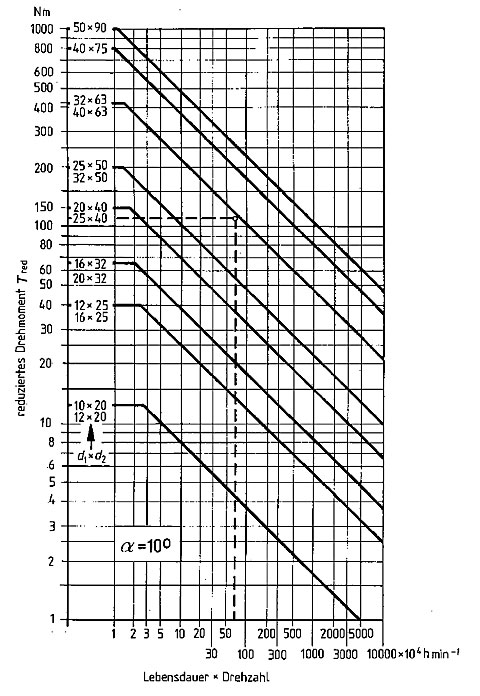
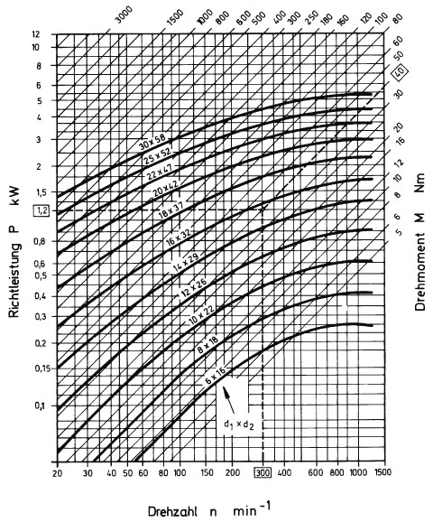
Image 1 shows the power and torque values transmitted by single precision universal joints during permanent operation with a deflection angle of α = 10°.
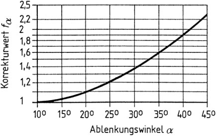
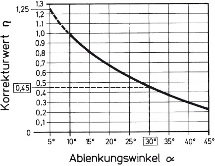
Image 2 shows the adjustment value to be taken into consideration for greater deflection angles. For deflection angles less than 10°, e.g. between 0° to 5° you may increase the standard power value shown in image 1 by 25%.
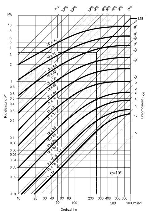
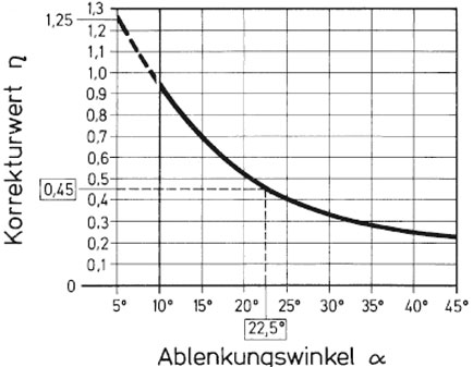
Image 2: Adjustment value in relation to the deflection angle